|
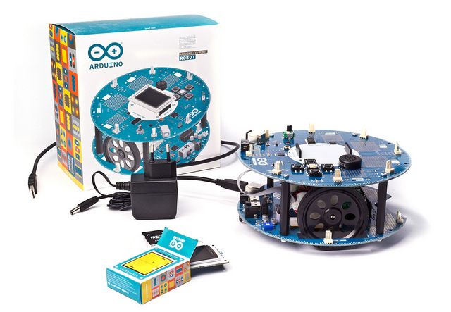
아두이노 로봇은 바퀴가 달린 첫 번째 공식 아두이노 로봇 입니다. 아두이노 로봇은 2개의 프로세서가, 2개의 보드에 각각 하나씩 장착되어 있습니다. 2개의 보드는 모터 보트와 제어 보드인데, 모터 보드는 말 그대로 모터를 제어하고, 제어 보드는 센서를 읽고 어떻게 동작할 것인지를 결정합니다. 각 보드는 모두 아두이노 IDE로 프로그래밍 가능한 완전한 아두이노 보드입니다.
모터 보드와 제어 보드 모두 Atmega32u4를 기반으로 한 마이크로컨트롤러 보드입니다. 아두이노 로봇이 가진 많은 핀들은 보드에 부착되어 있는 여러가지 센서와 액츄에이터와 미리 연결되어 있습니다.
아두이노 로봇에 프로그래밍하는 방법은 아두이노 레오나르도와 비슷합니다. 두 프로세서 모두 built-in USB 통신이 내장되어 있고, 추가적인 프로세서가 필요하지 않습니다. 이 방법으로 아두이노 로봇은 컴퓨터에 가상 시리얼 COM 포트로 인식됩니다.
아두이노가 항상 그래왔듯이, 아두이노 로봇 플랫폼의 모든 하드웨어, 소프트웨어, 문서 들은 오픈소스로서 자유롭게 이용될 수 있습니다. 이 말은 당신이 아두이노 로봇이 어떻게 만들어졌는지를 배워서, 그 디자인을 당신 로봇의 시작점으로 사용할 수 있다는 의미입니다.
Control Board Summary
| Microcontroller |
ATmega32u4 |
| Operating Voltage |
5V |
| Input Voltage |
5V through flat cable |
| Digital I/O Pins |
5 |
| PWM Channels |
6 |
| Analog Input Channels |
4 (of the Digital I/O pins) |
| Analog Input Channels (multiplexed) |
8 |
| DC Current per I/O Pin |
40 mA |
| Flash Memory |
32 KB (ATmega32u4) of which 4 KB used by bootloader |
| SRAM |
2.5 KB (ATmega32u4) |
| EEPROM (internal) |
1 KB (ATmega32u4) |
| EEPROM (external) |
512 Kbit (I2C) |
| Clock Speed |
16 MHz |
| Keypad |
5 keys |
| Knob |
potentiomenter attached to analog pin |
| Full color LCD |
over SPI communication |
| SD card reader |
for FAT16 formatted cards |
| Speaker |
8 Ohm |
| Digital Compass |
provides deviation from the geographical north in degrees |
| I2C soldering ports |
3 |
| Prototyping areas |
4 |
Motor Board Summary
| Microcontroller |
ATmega32u4 |
| Operating Voltage |
5V |
| Input Voltage |
9V to battery charger |
| AA battery slot |
4 alkaline or NiMh rechargeable batteries |
| Digital I/O Pins |
4 |
| PWM Channels |
1 |
| Analog Input Channles |
4 (same as the Digital I/O pins) |
| DC Current per I/O Pin |
40 mA |
| DC-DC converter |
generates 5V to power up the whole robot |
| Flash Memory |
32 KB (ATmega32u4) of which 4 KB used by bootloader |
| SRAM |
2.5 KB (ATmega32u4) |
| EEPROM |
1 KB (ATmega32u4) |
| Clock Speed |
16 MHz |
| Trimmer |
for movement calibration |
| IR line following sensors |
5 |
| I2C soldering ports |
1 |
| Prototyping areas |
2 |
|